Why EnergyBus?
The LEV market is currently characterized by numerous proprietary solutions for the communication between components and with chargers. Vendors of e-bikes cannot use components from different manufacturers due to a missing compatibility. On the contrary many e-bike manufacturers and customers wish to have replaceable components with different feature sets and the possibility to charge the e-bike or pedelec at public charging stations without the need to bring an own charger.
The EnergyBus e.V. association with currently around 70 member companies has dedicated itself to these targets. The objective of the association is to develop and to promote the EnergyBus standard. First successful results have been reached. In the national cycle traffic plan the German government has committed to develop a non-proprietary LEV charging infrastructure by 2020 and the international standardization within ISO and IEC has been started and pilot projects with public EnergyBus charging stations are running.
The EnergyBus connectors
Besides the communication between the components special connectors for EnergyBus devices have been developed by EnergyBus e.V. as well.
Properties of the EnergyBus connector:
-
Voltage up to 48V (power line)
Current up to 50A
2 pins for power (Powerline)
2 pins for 12V auxiliary voltage (for passive devices and to wake up deeply-discharged batteries)
2 pins for CAN communication
magnetic reverse polarity protection
unintended pulling out without damage is possible
CAN and CANopen
At the beginning of the EnergyBus development it has been evaluated which network protocol fits the requirements of EnergyBus. CAN, LIN, USB, I²C and RS485 have been taken into account, but CAN (Controller Area Network) has been chosen because of its robustness, flexibility and wide-spread use and availability. CAN is currently the dominating communication system in passenger cars and it provides broadcast communication and sophisticated error detection mechanisms. CAN is supported by nearly all manufacturers of microcontrollers and a CAN controller is integrated in most microcontrollers. It is a serial protocol which transmits its signal on the bit level as differential signals between to wires.
As CAN does not define an application layer protocol there was the need to define one. Instead of developing a new protocol from scratch, it has been decided to use CANopen as a basis for the communication. Therefore the EnergyBus e.V. association started a cooperation with the CAN in Automation association which maintains the CANopen specifications and its device and application profiles.
CANopen is a standardized communication protocol for embedded control networks. Its origin is the automation industry but in the meantime it covers a broad field of applications including railway application, off-road vehicles and special cars e.g. police cars and taxicabs.
The CANopen protocol provide a set of standardized services to exchange data between devices (nodes) in a network using CAN messages. One of the most important services is the PDO service (Process Data Objects) which allows the transmission of process data in CAN messages without protocol overhead. The SDO service (Service Data Object) provides a random access to all defined parameters of a CANopen device. Additionally the CANopen communication and application profiles define a set of parameters (object dictionary) which have to be available at all CANopen or profile compliant devices. CANopen networks can consist of 127 devices which can be addressed by its node-id. The node-id can be fixed (static or configurable by DIP switch) or dynamically assigned by the so called Layer Setting Service (LSS) which is similar to DHCP service. Device errors or alarms can be signaled in CANopen by so called Emergency messages whose content is also defined by profiles.
CANopen Application profile
In contrast to CANopen communication and device profiles, the application profiles define a complete application e.g. a LEV where components can be changed without reconfiguration. Application profiles define a fixed set of device properties and behavior and reduce the flexibility of CANopen to the needs of the application. The EnergyBus communication is defined in such an application profile – CiA 454 – which is officially called ‘Application profile for energy management systems’.
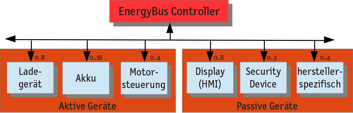
It defines a set of virtual devices with defined properties and configuration parameters. One or more virtual devices can be combined in a physical device. Currently the following virtual devices are specified:
Battery
Voltage Converter (Charger)
Motor control unit (MCU)
Display (HMI)
EnergyBus Controller as network master
Security Device
Additionally the CANopen application profile 454 defines the parameters in the object dictionary, a state machine for each virtual device, the process data which are sent by PDO with their cycle times and further properties. The profile covers further definitions for Emergency messages and it defines the use of dynamic node-id assignment by LSS and the maximum number of virtual devices.
EnergyBus devices are distinguished in active and passive devices. Active devices like the batteries, the chargers and the motor controller are connected to the power line. The passive devices instead are only powered by the 12V auxiliary voltage.
The profile additionally defines a bit rate of 250 kbit/s for CAN and recommends a CAN transceiver according to ISO 11898-5 – high-speed with low-power-mode. The new ISO 11898-6 transceiver with selective sleep functionality can be used as well.
Example: Battery
All EnergyBus devices must provide the following parameters (objects in CANopen terms) and allow access to them via EnergyBus:
supported virtual device
device status
device capability
rated voltage
control word
A battery must additionally support all mandatory parameters for active devices:
maximum continuous input current
maximum continuous output current
maximum and minimum voltage
allowed peak value for input current
allowed peak value for output current
actual voltage and current values
request of voltage or current limitation
And there are finally battery specific objects:
type of battery
actual capacity
rated capacity
temperature
cell voltages and currents
The EnergyBus specification additionally defines several optional parameters for each component. For batteries these are e.g. a deep discharge counter, a short cut counter, an over-temperature counter or a total Wh output counter and other objects. These optional parameters can be implemented by battery manufacturers to provide a history of the battery for after-sales service.
The firmware for the battery is mostly integrated in the battery management system and has to implement the following state machine as defined by the EnergyBus specification:
This state machine ensures that the battery is only attached to the power line if requested by the EnergyBus Controller.
The advantage of the EnergyBus standardization is that all EnergyBus compliant batteries (and other components) provide the same parameters and can be configured in the same way, so public charging stations will be able to charge different batteries from different manufacturers and EnergyBus tools will be able to communicate with all EnergyBus components.
Furthermore there can be more than one battery in an EnergyBus network and thus it is possible to connect a second battery to a pedelec to increase its range. Thanks to the standardized communication the connection can be realized without difficulties.
The application profile also defines a PDO mapping for each virtual device. For a battery these CAN messages have a defined structure and content depending on the number of the battery in the network which is assigned dynamically by the EnergyBus Controller, if more than one battery is present in the network.
EnergyBus Controller
The EnergyBus controller (EBC) is the central CANopen and control master in the EnergyBus network. The tasks are the assignment of node-ids by Layer Setting Services and the configuration of the devices by SDO. Additionally it performs a compatibility check for each device and the power line is only enabled if all devices signal that they are able to handle the provided voltage. Another task of the EBC is monitoring of all devices and reactions on device errors or loss of devices.
The virtual device EnergyBus Controller can also be implemented together with other components in one virtual device. For pedelecs the EBC will mostly be combined with the motor controller (MCU) in one physical device. Another use case is the implementation of EBC in a charger. In this case the EBC shall only be active, if it is the only EBC in the network.
From the CANopen point of view the EnergyBus Controller has to implement the following functionalities: network master, dynamic object dictionary, LSS master with FastScan, SDO client, Emergency consumer, Heartbeat consumer, PDO producer and consumer and additionally a SYNC producer with 100ms cycle time.
Extensions for isolated power grids
Isolated power grids can be found e.g. on solar-powered isolated farms in remote regions. The Fraunhofer institute for Solar Energy Systems(ISE) had started with the standardization of the energy management of isolated grids and has developed the Universal Energy Supply Protocol (UESP) which should be standardized as CANopen application profile as well. Because of the big cut set of LEV applications and energy management in isolated power grids, it has been decided to merge both use cases into the EnergyBus application profile CiA 454. The merger of both profiles lead to an abstraction and generalization of the components. Chargers for example have been extended to voltages converters that cover all kinds of current or voltage sources. Furthermore an EnergyBus network for stationary power grids may contain multiple power lines and gateways and there are additional modes of operation defined for master-less applications. This leads to new possibilities to extend and to couple the networks of both application fields. Both solar-powered charging stations for pedelecs as well as connection of pedelec batteries with the grid of a recreational vehicle (RV) – an isolated power grid – are in consideration. In the near future it will be possible that the batteries of a pedelec can be loaded from an RV and the pedelec can give power back to the RV if needed.
Implementation of EnergyBus
The EnergyBus specification and the basic CANopen communication profiles are freely available for members of the EnergyBus e.V.. Any member of the EnergyBus association can implement EnergyBus components. Because of the use of the CANopen protocol it is recommended to use a commercial-off-the-self CANopen stack which are available from different suppliers.
A further simplification of the development process can be achieved using the EnergyBus framework from emtas (www.emtas.de/en) which encapsulates all EnergyBus and CANopen services and state machines. Using this framework detailed knowledge of EnergyBus and CANopen is not required for developers of EnergyBus components.