
The ESI bit is a special bit in the CAN FD message. It is located after the BRS bit.
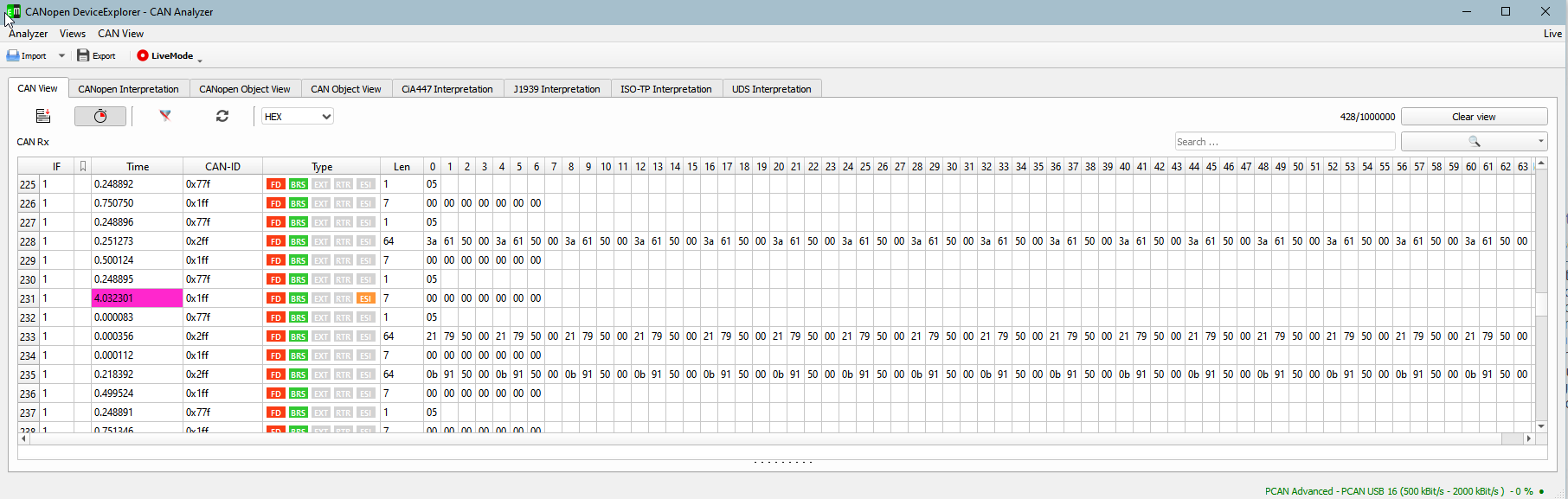
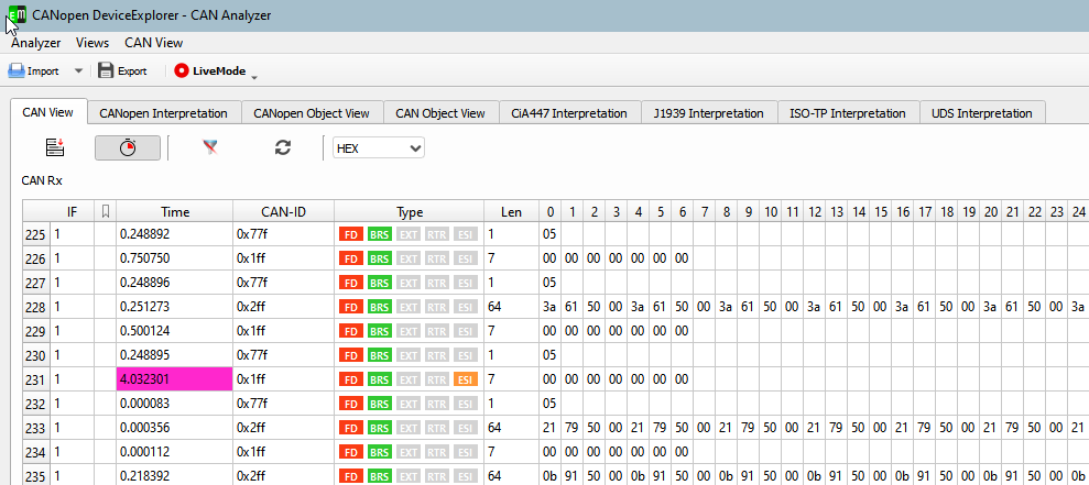
As shown in the CAN FD logging above, there is one CAN FD message where the ESI bit is set.
The ESI bit indicates that a specific node, the producer of the CAN FD message, is currently in the “error passive” state.
In the example above the situation has been provoked by removing the CAN cable while the node was cyclically transmitting CAN messages. Without any other node in the network, the CAN FD message is not acknowledge and the TX error counter of the device has exceed 127, so the CAN FD controller entered the state ‘error passive’.
After the CAN cable has been reconnected after approx. 4s, the 1st CAN FD message was sent with the ESI bit active.
There could be more then 1 message with an ESI bit, depending how many CAN errors occur when the cables are reconnected.
This transmission was successfully acknowledged and thus the error counter was decreased again and the ESI bit was reset.
The CAN FD logging was created using a CANopen FD example from emotas and the CANopen DeviceExlorer.
In the CAN frame the ESI bit itself is transmitted after the BRS (bit rate Switch) bit within the data phase of the transmission. Thus it is not possible anymore that 2 CAN FD message with the same CAN-ID and the same data are sent at the very same time by multiple transmissions. Different values of the ESI bit will cause a conflict in the data phase and thus to an bit error that leads to an error frame.